Thermal Properties Of Polymers : Analyzing Heat Deflection Temperature (HDT)
Thermal properties play a vital role in evaluating the product performance as well as
processability characteristics in the polymers.
Properties like specific heat and thermal conductivity are the determining factors in selection of processing parameters as well as designing the machines and tools for shaping of plastics.
The data are also useful in screening the materials for specific applications.
Terminologies
Heat capacity (C): Heat capacity is defined as the ratio of differential heat energy (dQ) and differential temperature (dT) for a material.
Mathematically, C = dQ / dT
Specific heat (c): Specific heat is defined as the heat capacity (C) per unit mass per unit volume. Specific heat is maximum at melting point in crystalline materials.
Thermal diffusivity : Thermal diffusivity measures the change in temperature which would be produced in unit volume of the substance by quantity of heat which flows in unit time across unit area of a layer of the substance of unit thickness with unit temperature difference between its faces.
Thermal Resistance (R): The temperature difference required to produce a unit of heat flux through the specimen under steady state conditions.
Thermal Conductance : Under study state conditions the heat flux required to product a unit temp. difference. is treated as thermal conductance.
Thermal yield stress: Test related to different types of stress conditions like bending, tension, & penetration under temperature to evaluate the materials behavior.
The tests are based on
1. Constant rate of temperature rise under selected arbitrary stress conditions until
the strain has reached some arbitrary level.
2. A selected constant test temperature & measurement of the degree of yield under
standardized conditions of stress.
3.The test measures the temperature or time at which the modulus deteriorates to
some specific level.

HEAT DEFLECTION TEMP (HDT)
Definition: Heat deflection temperature (HDT or heat distortion temperature is defined as the temperature at which an arbitrary deformation (0.010 inch) occurs when the test specimen subjected a stated load of either 66 or 264 psi. Heat deflection temperature (HDT) is a relative measure of a material’s ability to perform for a short time at elevated temperatures while supporting a load.
Significance:
1. HDT values are used to compare the elevated temperature performance of the materials under load at the stated conditions.
2. Used for screening and ranking materials for short-term heat resistance.
3. HDT values do not represent the upper temperature limit for a specific material or application.
4.The data are not intended for use in design or predicting endurance at elevated temperatures.
Test Method: ASTMD 648, ISO 75 -1 and 75-2
Specimen Dimension: 127mm (5 in.) x 13mm (½ in.) x 3mm (⅛ in.)
Test Apparatus:

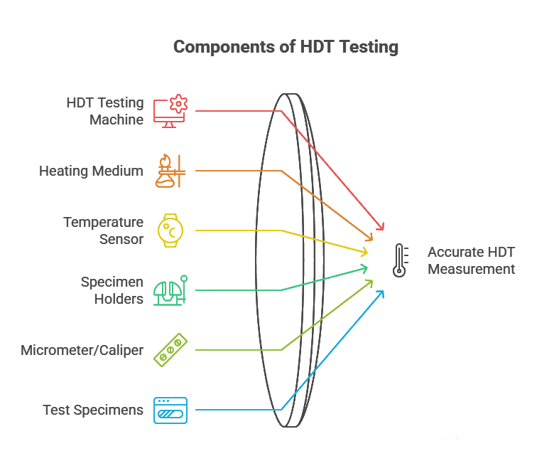
The apparatus broadly consists of the following:
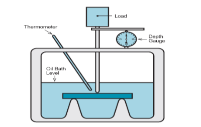
1. Specimen Supports: Metal supports for the specimen of 100 ± 2mm (3.94 ± 0.08 in.) apart, allowing the load to be applied on top of the specimen vertically and midway between the supports. The contact edges of the supports and of the piece by which load is applied shall be rounded to a radius of 3 ± 0.2mm (0.118 ± 0.008 in.).
2. Immersion Bath: A suitable liquid heat-transfer medium (oil-bath) in which the specimen shall be immersed. The bath is well-stirred during the test and shall be provided with a means of raising the temperature at a uniform rate of 2 ± 0.2 o C/min.
3.Deflection Measurement Device: Dial gage or any other indicating or recording device including electric displacement sensing apparatus may be used for the measurement of specimen deflection of at least 0.25mm (0.010 in.). It shall be readable to 0.01mm (0.0005 in) or better.
4.Weights: A set of weights of suitable sizes so that the specimen can be loaded to a fibre stress of 0.455 MPa (66 psi) ± 2.5% or 1.82 MPa (264 psi) ± 2.5%. The mass of the rod that applies the testing force shall be determined and included as part of the total load. If a dial gage is used, the force exerted by its spring shall be determined and shall be included as part of the load. Calculate the testing force and the mass that must be added to achieve the desired stress as follows:
F = 2Sbd 2 /3L
F 1 = F/9.80665
m w = (F – F s )/9.80665 – mr
Where:
F = load, N,
F 1 = load, kgf,S = fibre stress in the specimen (0.455 MPa or 1.82 MPa),
b = width of specimen, mm,
d = depth of specimen, mm,
L = width of span between supports (100mm),m w = added mass, kg,
F s = force exerted by any spring-loaded component involved N; this is a positive value if the thrust of the spring is towards the test specimen (downwards), or a negative value if the thrust of the spring is opposing the descent of the rod or zero if no such
component is involved and
m r = mass of the rod that applies the testing force to the specimen in kg.
Test Procedure:
- The width and depth of each specimen is measured at several points along the span. An average value of these readings is taken to obtain the nominal width and depth value of the specimen.
- The test specimens are positioned edgewise in the apparatus to ensure that they are properly aligned on the supports so that the direction of the testing force is perpendicular to the direction of the molding flow.
- The thermometer bulb sensitive part of the temperature measuring device shall be positioned as close as possible to the test specimen (within 10mm) without touching it.
- The liquid-heat transfer medium shall be stirred thoroughly to ensure that temperature of the medium is within 1.0 o C at any point within 10mm of the specimen.
- The bath temperature shall be at ambient temperature at the beginning of the test unless previous test have shown that, for the particular material under test, no error is introduced by starting at a higher temperature.
- Carefully apply the loaded rod to the specimen and lower the assembly into the bath.
- Adjust the load so that the desired stress of 0.455 MPa (66 psi) or 1.82 MPa (264 psi) is obtained.
- Five minutes after applying the load, adjust the deflection measurement device to zero or record its starting position. Heat the liquid heat-transfer medium at a rate of 2.0 ± 0.2 o C/min.
- Record the temperature of the liquid heat-transfer medium at which the specimen has deflected the specified amount at the specified fibre stress.
Calculation: The weight of the rod used to transfer the force on the test specimen is
included as part of the total load. The load (P) is calculated as:
P = 2Sbd2 / 3L
S = Max. Fibre stress in the specimen of 66 Psi / 264 Psi
b = Width of specimen
d = Depth of specimen
L = Width of span between support (4 in)


Post Comment