Dielectric Strength Evaluation of Polymers: ASTM D149, ISO 1325, and IEC 243-1 Comparative Analysis
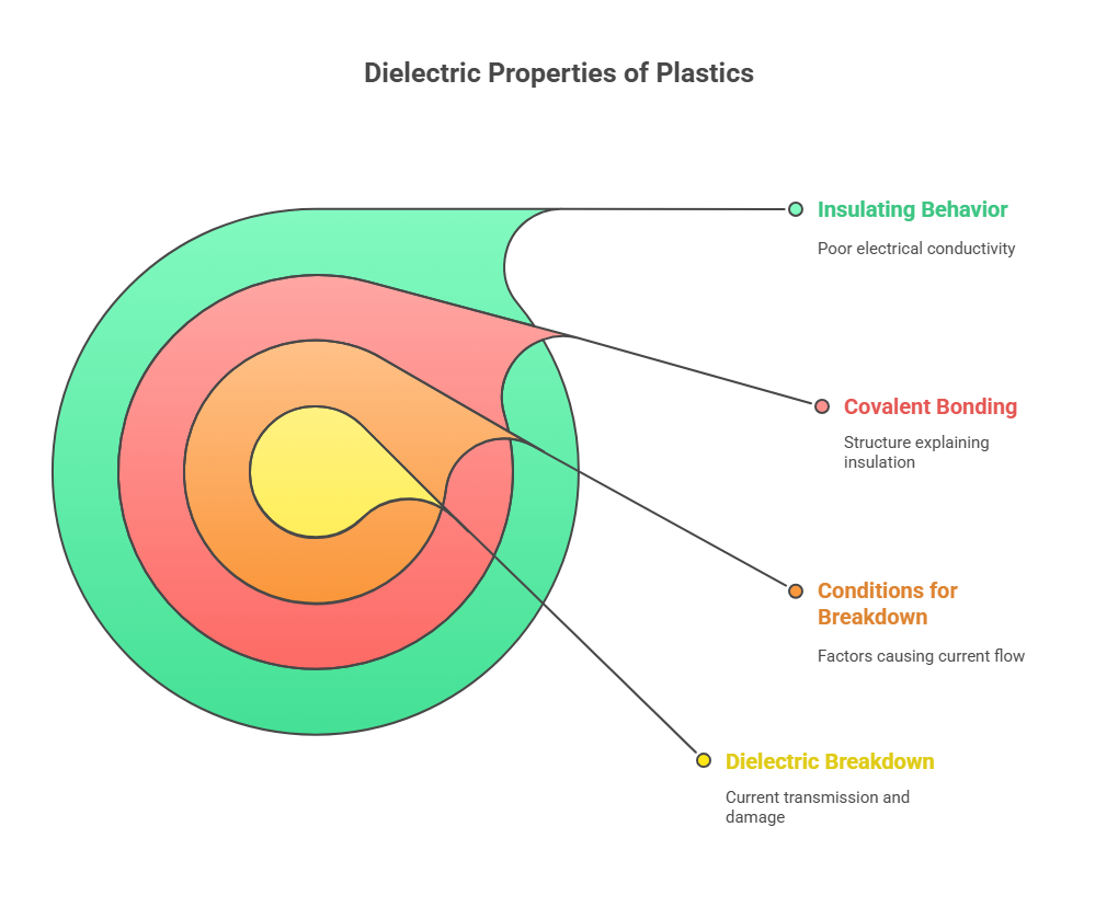
Most plastics are dielectrics or insulators (poor conductors of electricity) and resist the flow of a current. This is one of the most useful properties of plastics which makes it widely applicable as wire coatings, switches and other electrical and electronic products. Despite this, dielectric breakdown can occur at sufficiently high voltages to give current transmission and possible mechanical damage to the plastic.
The application of a potential difference (voltage) causes movement of electrons and when the electrons are free to move there is a flow of current. Metals can be thought of as a collection of atomic nuclei existing in a ‘sea of electrons’ and when a voltage is applied the electrons are free to move and conduct current. Polymers and the atoms that make them up have their electrons tightly bound to the central long chain and side groups through ‘covalent’ bonding. Covalent bonding makes it much more difficult for most conventional polymers to support the movement of electrons and therefore they act as insulators.

Polar and Non-Polar Plastics
Plastics can be broadly classified as ‘polar’ or ‘non-polar’ to describe their variations in behavior.
1. The polar plastics do not have a fully covalent bond and there is a slight imbalance in the electronic charge of the molecule. A simple example of this type of behavior would be that of the water molecule (H 2 O). The two hydrogen atoms are attached to the oxygen atom and the overall molecule has no charge. The electrons tend to be around the oxygen atom more than around the hydrogen atoms and this gives the oxygen a slightly negative charge and the hydrogen atoms a slightly positive charge. The overall water molecule is neutral and does not carry a charge but the imbalance of the electrons creates a ‘polar’ molecule. This ‘polar dipole’ will move in the presence of an electric field and attempt to line
up with the electric field in much the same way as a compass needle attempts to line up with the earth’s magnetic field. Examples of polar plastics are PMMA, PVC, PA (Nylon), PC and these materials
tend to be only moderately good as insulators.
2. The non-polar plastics are truly covalent and generally have symmetrical molecules. In these materials there are no polar dipoles present and the application of an electric field does not try to align any dipoles. The electric field does, however, move the electrons slightly in the direction of the electric field to
create ‘electron polarization’, in this case the only movement is that of electrons and this is effectively instantaneous. Examples of non-polar plastics are PTFE (and many other fluoropolymers), PE,
PP and PS and these materials tend to have high resistivities and low dielectric constants.
DIELECTRIC STRENGTH :
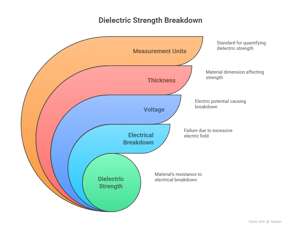
Definition: The maximum voltage required to produce a dielectric breakdown or electric failure through the material. Dielectric strength is expressed in voltage per unit of thickness such as V/mil, V/mm.
Significance:
1. This test is an indication of the electrical strength of a material as an insulator.
2.Higher the dielectric strength, better the quality of an insulator.
3. The higher the dielectric strength of a material the better its quality as an insulator.
4.The dielectric strength of an electrical insulating material is a property of interest for any application where an electrical field will be present. In many cases the dielectric strength of a material will be the determining factor in the design of the apparatus in which it is to be used.
Test Methods: ASTM D-149, ISO 1325, IEC 243 –1, BS 2782, BS 6564
Specimens Dimension: Film or sheet samples of a size sufficient to prevent flashing over.
The recommended specimen type for this test is a 100 mm plaque or larger of thickness between 0.8 or 3.2 mm
Equipment:
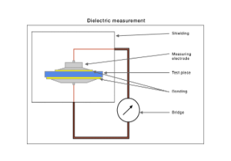
The instrument used for this test consists of the following:
(i) Voltage source: The test voltage from a step-up transformer supplied from a variable sinusoidal low-voltage source. The capacity of the source shall be sufficient to maintain the test voltage until dielectric breakdown occurs.
(ii) Voltage measurement: A voltmeter for measuring the rms test voltage. A peak- reading voltmeter may be used.
(iii) Electrodes: For a given specimen configuration, the dielectric breakdown voltage may considerably depend upon the geometry and placement of the test electrodes. The electrode surface must be kept clean and smooth and free from projecting irregularities. It is important that the original manufacture and
subsequent resurfacing of electrodes be done in such a manner that the specified shape and finish of the electrodes and their edges are maintained. Generally liquid metal electrodes, foil electrodes, metal shot, water or conductive coating electrodes are used. (iv) Test Chamber: The test chamber or area in which the tests are to be made shall be of sufficient size to hold the test equipment and shall be provided which interlocks to prevent accidental contact with any
electrical energized parts.

Test Procedure:
- It is insured that the main supply to the equipment is turned off.
- The test chamber is opened. The specimen is placed in the form of sheets or
plates having parallel plane surfaces and is of a size sufficient to prevent flashing
over, between heavy cylindrical brass electrodes which carry electrical current
during the test. - The main supply to the equipment is switched on. The voltmeter must show zero
reading. - The voltage is raised by regulator slowly till the flashover occurs.
- The voltage at flashover is noted which is the breakdown voltage.
There are three basic procedures for determining the dielectric strength of an insulator.
(a) Short time method :
Voltage is applied across the two electrodes and raised from zero to dielectric
breakdown at uniform rate. The rate of rise is generally 100, 500,1000 or 3000 V/sec
until the failure occurs. The failure is made evident by actual rapture or
decomposition of the specimen.
(b) Slow rate of rise :
The test is carried out by applying the initial voltage approximately to 50% of the
breakdown voltage. Subsequently, the voltage is increased at a uniform rate until the
breakdown occurs.
(c) Step-by-step method:
Approximately 50% of the test voltage is applied initially (usually for 1 minute) and
then increased in steps, each of which is held for one minute.
Calculation :

Factors Influencing:

1. Specimen Thickness: The dielectric strength of an insulator varies inversely with the fractional power (0.4) of the thickness. The thicker specimen requires higher voltage to achieve the same voltage gradient.
2. Temperature: Dielectric strength decreases with the increase in the temperature of the specimen.
3.Electrodes: Dielectric strength of a material is effected by the electrode geometry, the electrode area, and the electrode base material composition. Generally the breakdown voltage decreases with increasing electrode area.
4. Time: The rate of voltage application significantly alters the test results. Dielectric strength values obtained using step-by-step methods are lower than those obtained by the short-term test.
5. Mechanical stress: Mechanical stress tends to reduce the dielectric strength values substantially.
6. Processing: Defects such as poor weld lines, voids, bubbles and flow lines brought forth by poor processing practices tend to reduce the dielectric strength to nearly 30-60%.


Post Comment