Injection Moulding Basics (Part 1): Everything You Need to Know
In the mass-production manufacturing technique known as injection molding, molten materials—most frequently thermoplastic polymers—are injected into a mold, where they cool and solidify into the required shape to produce three-dimensional objects.
This flexible, high-volume method creates similar, robust, and long-lasting parts at a low cost per unit, which makes it perfect for common plastic products like kitchen appliances, electrical enclosures, and auto parts.
This process is used for thermoplastic materials and other polymeric materials which may be successively melted, reshaped and cooled. Injection moulded components are a feature of almost every functional manufactured article in the modern world, from automotive products through to food packaging.
This versatile process allows us to produce high quality, simple or complex components on a fully automated basis at high speed with materials that have changed the face of manufacturing technology over the last 50 years or so. Injection moulding is suitable processing method for following materials:
- Thermoplastics
- Elastomers
- Rubbers
- Thermosets
- Composites
- Foamed plastics
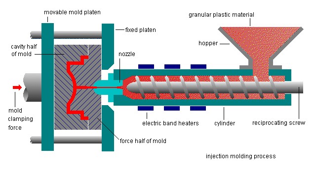
Injection moulding machines consist of two basic parts, an injection unit and a clamping unit.
Injection moulding machines differ in both injection unit and clamping unit.
Injection Moulding Cycle & Process
- The injection moulding process occurs cyclically.
- Typical cycle times range from 10 to 100 seconds and are controlled by the cooling time of the thermoplastic or the currying time of the thermosetting plastic.
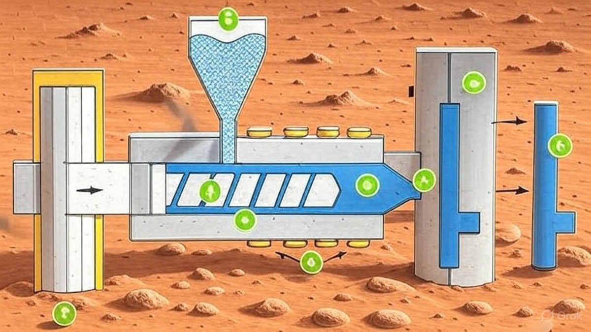
- The plastic resin in the form of pellets or powder is fed from the hopper and melted.
- In a reciprocating screw type injection moulding machine, the screw rotates forward and fills the mould with melt, holds the melt under high pressure and adds more melt to compensate for the contraction due to cooling and solidification of the polymer.
- This is called the hold time.
- Eventually the gate freezes, isolating the mould from the injection unit, the melt cools and solidifies. Next the screw begins to rotate and more melt is generated for the next shot.
- In the soak time the screw is stationary and the polymer melts by heat conduction from the barrel to the polymer.
- The solidified part is then ejected and the mould closes for the next shot.
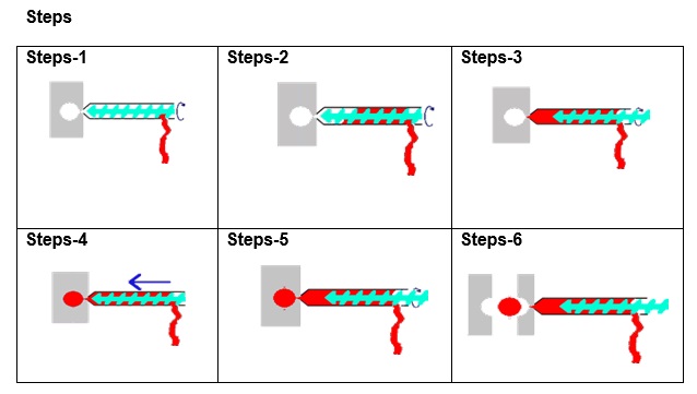
Step 1: The uncured resin is fed into the machine in the form of a continuous strip.
Step2: The uncured resin is worked and warmed by an auger screw in a temperature controlled barrel.
Step 3: As the resin stock accumulates in the front of the screw, the screw is forced backwards. When the screw has moved back a specified amount, the machine is ready to make a shot.
Step 4: With the mould held closed under hydraulic pressure, the screw is pushed forward. This forces the resin into the mould, similar to the action of a hypodermic syringe.
Step 5: While the resin cures in the heated mould, the screw turns again to refill.
Step6: The mould opens and the part can be removed. The machine is ready to make the next shot, as soon as the mould closes.
Problems encountered in Injection Moulding
There are many details to pay attention in injection moulding which affects the physical properties, they may even cause to the failure of the moulding.
- Jetting occurs when polymer melt is pushed at a high velocity through restrictive areas, such as the nozzle, runner, or gate, into open, thicker areas, without forming contact with the mould wall. This leads to part weakness, surface blemishes, and a multiplicity of internal defects.
- Air can trapped by converging polymer melt fronts or because it failed to escape from the mould vents or mould inserts, which also act as vents.
- A short shot is a moulded part that is incomplete because insufficient material was injected into the mould. It can be caused by entrapped air, insufficient machine injection pressure (resulting from high melt resistance and a restricted flow path), pre-mature solidification of the polymer melt, and machine defects.
- A sink mark is a local surface depression and a void is a vacuum bubble in the core. Sink marks and voids are caused by localized shrinkage of the material at thick sections without sufficient compensation when the part is cooling.
- A weld line (also called a weld mark or a knit line) is formed when separate melt fronts traveling in opposite directions meet. The formation of weld lines can be caused by holes or inserts in the part, multi-gate cavity systems, or variable wall thickness where hesitation or race tracking occurs. The weld lines are undesirable when the strength and the surface quality are important.
Raw Materials
Most raw materials can be used. The resin is in pellets before processing.
- Acrylonitrile-Butadiene-Styrene (ABS)
- Nylon
- Polycarbonate (PC)
- Polypropylene (PP)
- Polystyrene (PS)
Advantages
- High production rates
- Design flexibility
- Repeatability within tolerances
- Can process a wide range of materials
- Relatively low labour
- Little to no finishing of parts
- Minimum scrap losses
Disadvantages
- High initial equipment investment
- High start up and running costs possible
- Part must be designed for effective moulding
- Accurate cost prediction for moulding job is difficult
Applications
Containers, household goods, auto components, electronic parts, flower pots.


Post Comment